Selecting die V opening
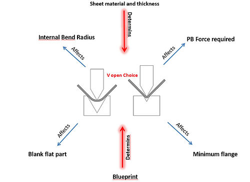
The V opening used deeply affects the results we get on our part
The V opening we select is determined by the blueprint of our part and the sheet specs and thickness.
let's see why:

How the blueprint conditions our V selection:
The blue print details might call for a specific operation that will determine or condition our V die selection.
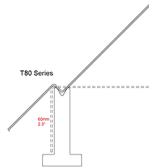
A hemming detail will determine that we need a hemming die set
A back bend present on the part will limit our choices to dies with enough height to allow for such operation

A large radius bend will require larger V opening and of course a short flange will call for a V opening that's not wide enough to make the flange fall into it.
Non the less, a certain material type and thickness called in the blueprint for a part, might require a specific V opening. such is the case of abrasive resistant steels.
All these aspects limit the choices, condition the options and in some cases simply force us to choose a certain V opening
There are bending apps or tables that will help us choose the correct V.
They all start by asking the material type and thickness and they give back an ideal V opening with some options.
Each option implies a series of consequences to radius, force and minimum flange.
Let's see why this happens.
How V opening affects the iR of our part

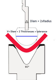
Although some fabricators are used to relating the internal radius of the part with the punch radius, this is not always how bending works. Most of the times the iR is a result of the V opening used.
On most parts we bend, the ideal iR = 1 thickness. This is true because if the radius was smaller than 1 thickness, it means that the material taken from the radius is gone somewhere. On plate bending we see how the bend shows "side bumps" if the iR is smaller than 1 thickness.
Of course an iR larger than 1 thickness is not a problem form this point of view.
So, how does it work between V opening and iR?
Well, first of all it depends on the material UTS. The stronger the material the larger the iR will result on a given V opening.
Empirically we know for example that on mild steel the iR is equal to 1/8 of the V used. While on stainless steel this ratio is 1/6 of the V.
Other materials like Hardox can never be bent to obtain iR=1t because they would crack due to lack of ductility.

The above ratios do tell us something quite interesting. They are the ground on which is based the most common rule of thumb for every job shop:
V = t x 8 (or 6 in small gauge)
This rule has some variations. The most common being that on thick plate we use V=10xt. The reason for this is that thicker plate tends to loose some ductility, so we use a larger V opening to distribute the force on a larger area and avoid cracks in the sheet.
How V opening affects our flat blank (and how we cut it on the laser)
Let's think about this for a second: The larger the V opening we use the larger the radius we will obtain. But:
What happens to the blank, and how do we need to cut it according to what the iR of the part will be?
If we measure the flanges of our part from the outside dimensions, then the larger the iR is, the shorter we need to cut the flat blank (think about it. It's shorter to go through the diagonal of the corner than it is to go around it).
In the example shown here we can see the extra material (in red) of the part once we bend it with a larger V opening (obtaining a larger iR).
Many PB operators face this problems when the flat blanks cut on the laser were drawn with no consideration of the V opening that was going to be used on the press brake operation.
To avoid flange discrepancy: The V die on the pres brake must be part of the calculation on the blank size we cut on the laser

V die opening is essential in the calculation of a correct flat blank
How V opening affects our flange size
Probably the most known and intuitive effect from the V we select is that we need a flange that is long enough to go across the opening.
We have many tables and charts showing what the flange needs to be for any given V opening. Let's see how these charts are created, so we can understand better what is going on.
Using trigonometry we can easily determine that when we get a 90° bend, our flange is the leg of a right angle triangle with the V opening being the hypotenuse
By simple trigonometry this tells us that L1=0.707 x h (where h is the V opening)
Since there's a radius formed and we are measuring the minimum flange size from the INSIDE, we need to subtract half a radius. So we need to be a little more tight than what trigonometry suggests.
On MS 90° bends
min. flange = 0.66 x V

If you want to know the OUTSIDE min flange just add 1 thickness.
An acute bend calls for a longer minimum flange in order to go deeper into the V opening. That's why we need to increase or decrease the minimum flange size according to the desired angle on the part:
-
30° = min Flange x 1.6
-
60° = min Flange x 1.1
-
120° = min Flange x 0.9
-
150° = min Flange x 0.7
How V opening affects the force needed
Easily enough we can all understand that a lot more force is required in order to brake a sheet into a tighter V opening than what's required if the V is larger.
But how do we calculate the force (in tons) that is required to brake a given material type into a certain V opening?
Nowadays we just let the CNC run the numbers for us. Nevertheless it's important for us to be able to estimate this force in order to make decisions on the spot without having to use the CNC (which might be running actual parts) or a simulations software
The following is a simplification of a formula used in order to calculate the maximum weight a bridge can support before deforming. This is the reasoning and the calculations that our CNC's are doing for us.

Of course, if you need to calculate some bending parameters of force, flange or radius simply use my Bend Calculator!!!